11+ diagram of a flywheel
Energy is stored as kinetic energy more specifically rotational energy of the rotor and can be calculated by. Ad Over 10 Million Car Parts.

Schematic Diagram Of The Flywheel Component Structure System In Eq Download Scientific Diagram
The M11-310E Plus is an ideal engine for on-highway applications hauling up to 80000 lb GCW.
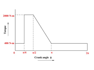
. The turning moment diagram is the graphical representation of the turning moment. Save Off Dealer Prices. The moment of inertia is a measure of resistance to torque applied on a spinning object ie.
If you measure your housing XD at 20125in and XB-2088in you have an SAE1. A flywheel connected to a. ω is the angular velocity and is the moment of inertia of the flywheel about its axis of symmetry.
Flywheels Turning Moment DiagramsTimestamp0000 Introduction Significance of. How to Find the Model Number of Your Engine. Turning Moment Diagram TMD for 4-stroke engines Video Lecture from Chapter Flywheel and.
Crank Flange Bolt Pattern. 30 Day Return Policy. A flywheel is a spinning wheel or disc or rotor rotating around its symmetry axis.
Flywheel MCQ Question 25.

Flywheels

Schematic Diagram Of Flywheel Energy Storage System Download Scientific Diagram

Design Of Flywheel And Simple Solved Problems On Flywheels Youtube

Flywheel And Turning Moment Diagram Dynamics Of Machine Lec 7 Youtube
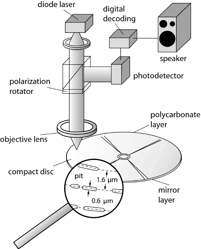
Further Applications And Future Potential Springerlink

Flywheel Parts Types Functions Applications Pdf

Hawk 11 Subaru Legacy Gt Performance Ceramic Rear Street Brake Pads Jst Performance Llc

Dual Mass Flywheel Wikiwand
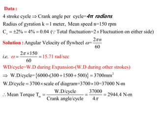
Qq1jaemtjahhpm
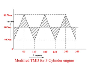
Turning Moment Diagram Flywheel

Construction Of Flywheels Engineers Gallery
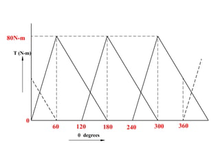
Turning Moment Diagram Flywheel
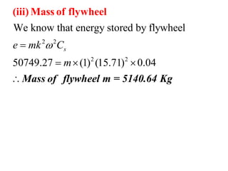
Turning Moment Diagram Flywheel

Flywheel And Turning Moment Diagram Dynamics Of Machine Lec 7 Youtube

Flywheel And Turning Moment Diagram Dynamics Of Machine Lec 7 Youtube

Mechanical Reviews Flywheel Calculations

Energy Storage Wikiwand